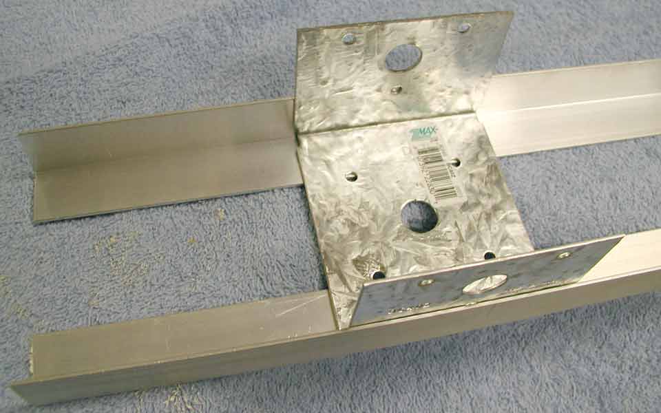
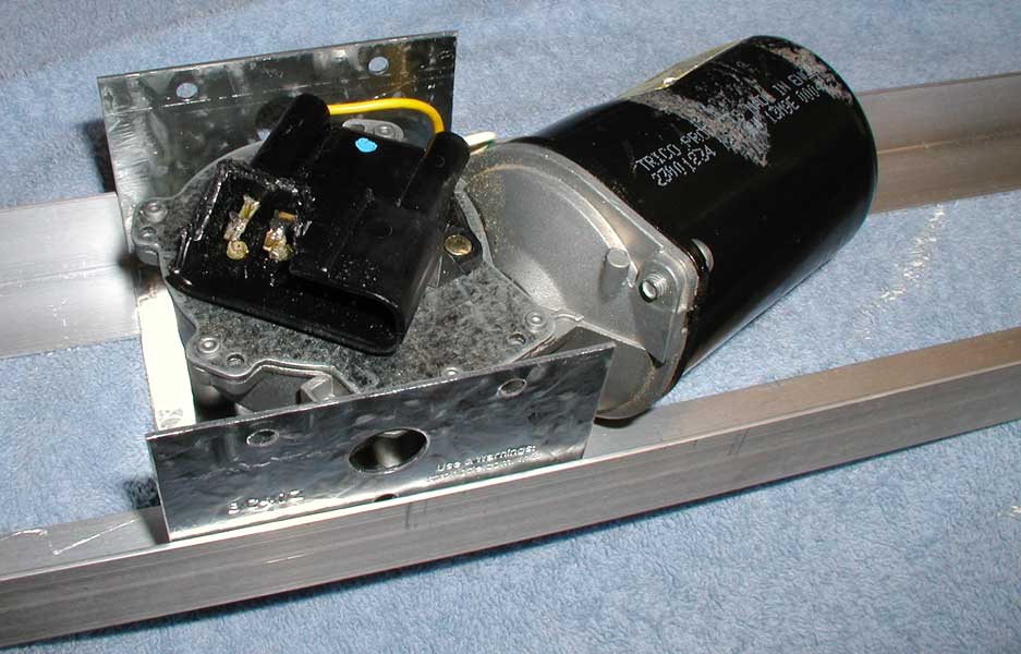
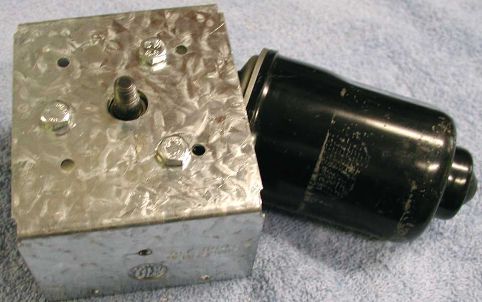
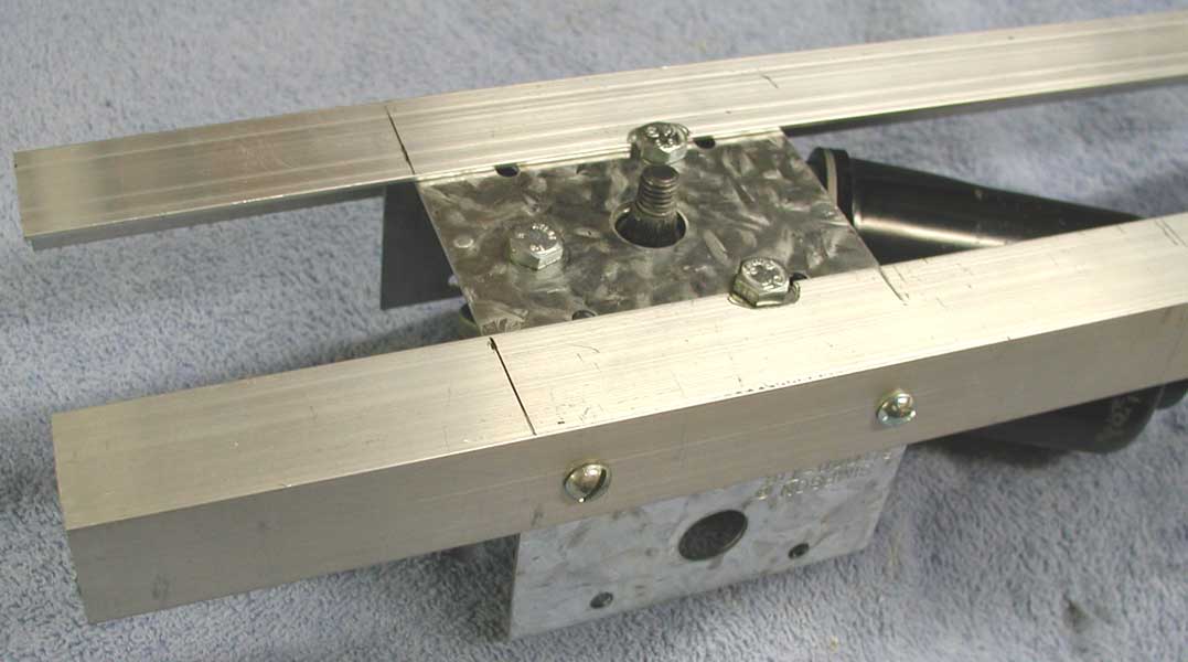
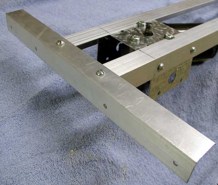
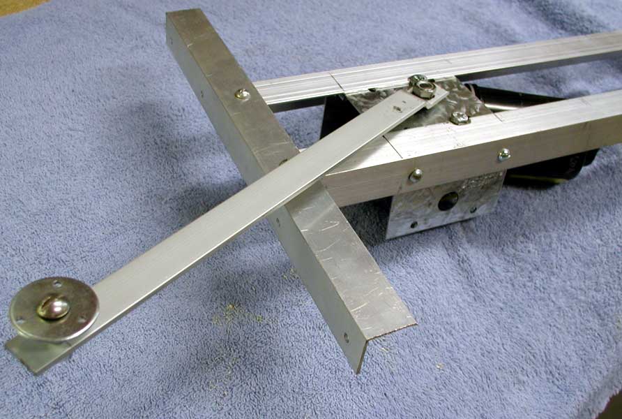
We'll
use the 4x4 post cap as the bracket for mounting the motor.
Start
by cutting two pieces of the 1" angle aluminum, 20" long.
(For planning purposes, we'll need the two 20" pieces and also
two 12" pieces)
Temporally
place them on either side of the post cap as shown at left.
Remove
the rotating arm that comes with the motor. We won't be needing this.
Be sure to save the nut and washer.
Temporarily
place the motor on the bracket as shown right. The motor shaft goes
through the large hole in the center of the post cap.
Rotate
the motor so that it fits between the two pieces of angle aluminum.
With
the shaft of the motor centered in the hole in the post cap, using a
marker, trace around the three mounting posts of the motor so as to
leave markings on the post cap showing where to drill holes to mount
the motor.
Using
a 1/4" drill bit, drill through the centers of the markings from
the previous step.
If you
marked and drilled everything perfectly, the motor mounting holes should
line up with the holes in the bracket. Adjust as necessary.
Using
the 6mm screws and three of the 1/4" lock washers, mount the motor
to the bracket. It should look like the picture to the left.
In this
step, we'll modify the two 20" pieces of angle aluminum so that
they'll fit around the motor mount screws.
Make
a mark on each piece of the angle aluminum 3" in from the end.
Set
the two angle aluminum pieces over the motor bracket with the 3"
marking even with the edge of the motor mount, as shown right.
Mark
each piece of the angle aluminum where the motor mount screws interfere.
Using
the appropriate tools, trim away the aluminum to fit around the motor
mount screws (I used a nibbler tool and a round file. You could also
just file away the aluminum or notch it with a hacksaw). Be careful
not to cut too much material away.
Next, we'll mount the motor mount to the two 20" pieces of angle
aluminum.
Holding one piece of the angle aluminum in place, with the 3"
mark lined up on the edge of the motor mount, drill a hole for a #10
screw about 1/4" in from the edge of the motor mount and halfway
down the angle aluminum.
Place a #10-32 x 1/2" screw through the hole and fasten with
a lock washer and nut.
Repeat for a second hole as shown in the picture on the left.
Now do the same thing for the angle aluminum on the other side.
In this
step, we'll attach two cross pieces of angle aluminum. These will be
used to mount the motor mechanism to the wooden frame.
Cut
two pieces of angle aluminum, 12" long.
Center
one piece of the aluminum on the motor mechanism angle aluminum as shown
at right.
Drill
two holes for #10 screws and attach the cross piece to the motor mount
using two more of the #10, 1/2" screws, lock washers and nuts.
Repeat
the same procedure for the other end of the motor mount angle aluminum
pieces.
Note
in the picture at right, I have also drilled four holes in the cross
piece of angle aluminum for later mounting to the 2x2 wood. This would
be a good time to drill those holes in both cross pieces.
Now,
we'll make the arm that goes on the motor shaft.
If you
haven't done so already, cut a 12" long piece of the 3/4"
flat aluminum stock.
On one
end, drill a 1/4" hole, centered on the stock, about 5/8"
in.
On the
other end, drill a 5/16" hole, again, centered on the stock and
5/8" in.
We need
an offset bend to keep the rotating arm clear of motor mounting hardware.
On the
end of the arm that has the 5/16" hole, mark a line across the
arm at 1" and another at 1 1/4" in from the end.
Clamp
the arm in a vise at the 1 1/4 "mark, with the short part of the
arm exposed.
Using
a hammer, bend the short piece of aluminum arm to about a 45 degree
angle. Use multiple, somewhat gentle blows with the hammer instead of
pounding real hard.
Now,
flip the piece over in the vise and align the 1" mark with the
top of the vise. The long piece of the arm is now exposed above the
vise.
Bend
the arm in the opposite direction until the short section with the hole
is parallel to the longer section. The bend should look something like
the picture on the right.
Here,
we'll prepare a fender washer to which the lines controlling the skeletons
will be attached.
Drill
three small holes, evenly spaced, about 1/8" from the edge of the
washer as shown to the left. You'll need nice clean holes to avoid cutting
the fishing line which will be attached later.
Put
the washer on the 1/4" x 1" screw and add two 1/4" nuts
as shown at right.
Leave
about 1/16" space between the washer and the top nut to allow the
washer to spin freely. Tighten the nuts against each other to lock them
in place.
Mount
the washer mechanism to the end of the arm with the 1/4" hole using
a 1/4" lock washer and 1/4" nut.
Mount
the arm onto the motor shaft as shown right.
You'll
want to tighten the shaft nut fairly tight so that the hole in the arm
is slightly forced onto the tapered part of the motor shaft. This should
keep the arm from slipping when the motor rotates.