Kicking Legs
by Scary Terry
|
|
Kicking Legs by Scary Terry |
|
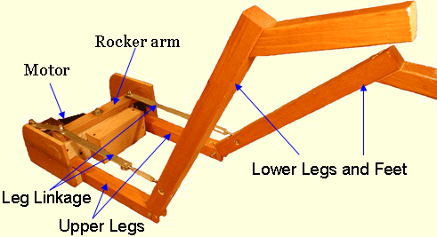
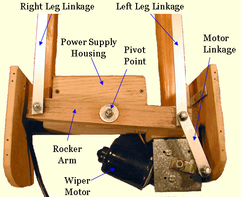
Hi All. Here's a description of making a set of kicking legs for use in your Halloween displays. The idea is based on the "Kicking Witch" from "Dan's Halloween Page". I use a set of these under a lawn mower, but I think they can have numerous other uses in your haunt limited only by your imagination. The following presents pictures and descriptions on how I did it. It is by no means a definitive how-to. I encourage you to make changes to fit your own needs or just to make it work better. These kicking legs use a wiper motor to drive the mechanism. See my wiper motor page for detailed information on working with wiper motors. Note: This design has been modified as of 12/2005. The new design repositions the motor and improves on the leg linkage which makes for a smoother operation. I'd like to thank Tom of Maniac Mansion for his design ideas on this. |
|
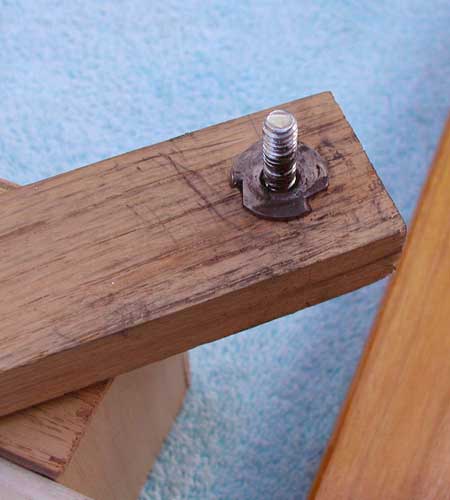
To the right and below are the individual parts that make up the kicking legs.
|
 |
||||
|
 |
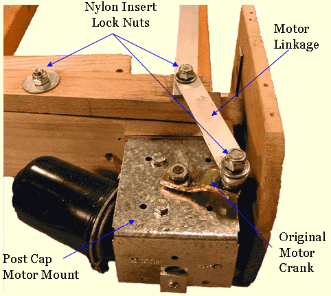 |
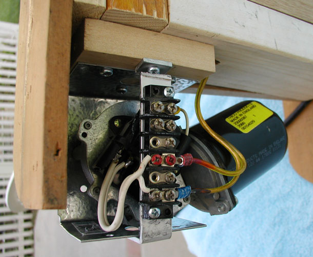
The motor is mounted using a 4x4 post cap (i.e. Simpson BC40, available in hardware stores and home centers) which is screwed to the framework. The motor mount is supported by a piece of aluminum bent to form a bracket as seen at the lower part of the photo at left and in the photo below. The wiring terminal is attached to that piece of aluminum (Note: if you look closely at the photo, you'll notice that the aluminum strip is broken. I didn't see this at the time the photo was taken. The break was probably due to trying to make too tight of a bend in the aluminum.)
The motor linkage is attached to the original motor crank using a 5/16" bolt which is tightly attached the the crank using a lock washer and nut. I then applied a 5/16" washer, the motor linkage, another washer and the nylon insert lock nut. The nut is backed off about 1/2 turn from being fully tight which allows the motor linkage the freedom to rotate without too much slop. |
| On to page 2 |
|
|
Halloween Home | last update 12/2016 |