Onboard Fogger Timer


Hi Halloweeners,

The following is a description on how I added an "onboard" timer to an inexpensive fogger. I call it "onboard" because it's built in to the existing fogger case instead of added on to the remote. The advantages of doing it this way are: there's a convenient source of power for the timer circuit and there's not a bunch of external cables to clutter things up. The remote for the fogger will still work normally just in case you need to trigger 
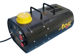
it manually. The fogger I used for this project is the "lite F/X" fogger purchased from K-Mart for about $40. This is a great fogger to use for this application because there's ample room inside the case for the circuitry. This circuit will certainly work on other foggers, but in some cases, may have to be added in an external box.

If you are considering performing this timer modification to your fogger, I must give this WARNING: This modification of the fogger requires opening the case and exposing yourself to potentially deadly voltages. DO NOT attempt it if you are unfamiliar with electrical circuitry. Never work on the fogger with it plugged in. Additionally, opening the case and installing this modification will void the warranty on the fogger.

Below is the schematic and parts list for the timer circuit. On the next page are some pictures of the installation and on the following page is an alternate circuit using a 555 timer.


Notes on the circuit:

  • The top portion of the schematic is a basic 5 volt power supply. Current draw of the CMOS timer is very low, so a small 120/12 volt transformer can be used. I mounted the 7805 regulator in a heat sink (see picture at right) but it probably isn't necessary. Switch SW1 turns the timer circuit on and off.
  • CMOS 4528 is a dual monostable multivibrator (English translation: two timers in one). As drawn below, the left side controls the spacing between fog pulses and the right side sets the length of the fog pulse. These times are set by the r/c components attached to pins 2 and 14 respectively. The spacing times range from about 8 to 50 seconds (adjustable with pot R1) while the pulse length times are about 1 to 10 seconds (adjustable with pot R3).
  • Resistors R2 and R4 set the minimum times.
  • The normally open switch terminals of relay K1 are wired to the fogger pump circuit. In the above mentioned fogger, the pump current draw is only 500 ma (1/2 amp) so a relay with 1 amp rated terminals will work fine (I used a minature realy from All-Electronics #RLY-405. It's the little green thing on the circuit board). The relay is wired across the terminals on the fogger remote connector that go to the switch on the remote. These can be found using an omhmeter across the pins on the remote and pushing the remote button.
  • The entire circuit (except SW1, L1, R1, R3 which are mounted to fogger case) fits nicely on a Radio Shack (276-150) or MCM Electronics (21-4590) circuit board.
  • The only thing I don't like about this circuit is that when it is first powered up, the capacitors (C1 in particular) takes a while to charge up so the timer is disabled for up to a minute. After that, it is very stable and reliable.
 
Timer board and transformer as mounted in the fogger


  Click here for a pdf version of the schematic  

 
Parts List
 
  ID Description ID Description  
SW1 SPST toggle switch U1 7805 5volt voltage regulator
L1 120/12 volt transformer U2 CMOS 4528
D1 1A bridge rectifier R1, R3 1 meg linear taper pot
D2 1n4001 diode R2, R4 100k 1/4 watt resistor
C1 220uf 16 volt capacitor R7 10k resistor 1/4 watt resistor
C2 47uf 16 volt capacitor Q1 NPN transistor i.e. 2N2222
C3, C7 0.1uf 50v capacitor K1 5v SPDT relay, 1 amp contacts
C4 0.33uf 50v capacitor   16 pin IC socket (recommended)
C5 2200uf 25v electrolytic capacitor   Circuit board
C6 470uf 16 volt capacitor    
       

  Halloween Home On to Page 2 last update 5/2004